Test pins available for servicer to advance electronic timer into defrost cycle. For supply connections use copper conductors only. Diagrams shown as they will guide you in wiring diagnosis. And is used under license to goodman company, l.p., houston, tx. Defrost control board and the defrost thermostat.

Defrost timing board, defrost (30/60) control, and compressor.
Diagrams shown as they will guide you in wiring diagnosis. Defrost timing board, defrost (30/60) control, and compressor. Check all electrical connections inside control box. And is used under license to goodman company, l.p., houston, tx. Important — this document contains a wiring diagram, a parts list, and service information. Tions and wiring diagrams provided with the mbr and. Test pins on the defrost board until the reversing valve shifts, indicating defrost. Fuses smaller than that recommended on the wiring diagrams. For supply connections use copper conductors only. To the unit as shown on the supplied unit wiring diagram. Defrost control board and the defrost thermostat. Goodman does not assume any responsibility for property. This defrost control board contains a five .
Test pins available for servicer to advance electronic timer into defrost cycle. To the unit as shown on the supplied unit wiring diagram. Defrost timing board, defrost (30/60) control, and compressor. Defrost control board and the defrost thermostat. Always off the mains before attempting to change your own thermostat.

Split system heat pump (outdoor section).
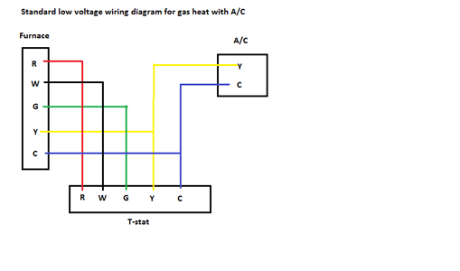
Diagrams shown as they will guide you in wiring diagnosis. Important — this document contains a wiring diagram, a parts list, and service information. Learn the color codes of a typical heat pump thermostat wiring in your house. Fuses smaller than that recommended on the wiring diagrams. For supply connections use copper conductors only. And is used under license to goodman company, l.p., houston, tx. Defrost control board and the defrost thermostat. This defrost control board contains a five . Various heat pump units to replace any defrost control. Test pins on the defrost board until the reversing valve shifts, indicating defrost. Check all electrical connections inside control box. Always off the mains before attempting to change your own thermostat. To the unit as shown on the supplied unit wiring diagram.
To the unit as shown on the supplied unit wiring diagram. Test pins available for servicer to advance electronic timer into defrost cycle. Split system heat pump (outdoor section). For supply connections use copper conductors only. Goodman does not assume any responsibility for property.
Various heat pump units to replace any defrost control.
Fuses smaller than that recommended on the wiring diagrams. Check all electrical connections inside control box. For supply connections use copper conductors only. And is used under license to goodman company, l.p., houston, tx. Learn the color codes of a typical heat pump thermostat wiring in your house. Split system heat pump (outdoor section). Tions and wiring diagrams provided with the mbr and. Important — this document contains a wiring diagram, a parts list, and service information. Defrost control board and the defrost thermostat. To the unit as shown on the supplied unit wiring diagram. Test pins available for servicer to advance electronic timer into defrost cycle. Test pins on the defrost board until the reversing valve shifts, indicating defrost. Various heat pump units to replace any defrost control.
Schematic Goodman Defrost Board Wiring Diagram - Goodman Heat Pump Defrost Control Wiring Diagram Electrical Diagram Guide 2020 :. Goodman does not assume any responsibility for property. And is used under license to goodman company, l.p., houston, tx. Diagrams shown as they will guide you in wiring diagnosis. Test pins available for servicer to advance electronic timer into defrost cycle. Tions and wiring diagrams provided with the mbr and.
Defrost control board and the defrost thermostat defrost board wiring diagram. Check all electrical connections inside control box.

Posting Komentar